
WolkenThermometer (WiFi-Sensor)
a smart and self-powered sensor for your home
published under the creative commons attribution and share alike.
![]()
For now (2015-03-01) this page is a mixture of concept, documentation and product preview. Please stay tuned for the final product and software!
Pleas visit the News-site for chronological updates: WolkenThermometer-News
In addition you can sign up to the news letter:
<HTML> <!– Begin MailChimp Signup Form –> <link href=„cdn-images.mailchimp.com/embedcode/classic-081711.css“ rel=„stylesheet“ type=„text/css“> <style type=„text/css“> #mc_embed_signup{background:#fff; clear:left; font:14px Helvetica,Arial,sans-serif; width:500px;} /* Add your own MailChimp form style overrides in your site stylesheet or in this style block. We recommend moving this block and the preceding CSS link to the HEAD of your HTML file. */ </style> <div id=„mc_embed_signup“> <form action=„zeilhofer.us10.list-manage.com/subscribe/post?u=c851e250d0958ca58308319de&id=78f0bc7503“ method=„post“ id=„mc-embedded-subscribe-form“ name=„mc-embedded-subscribe-form“ class=„validate“ target=„_blank“ novalidate>
  <div id="mc_embed_signup_scroll">
<h2>Subscribe to the Newsletter</h2>
<div class=„mc-field-group“>
<label for="mce-EMAIL">Email Address </label>
<input type="email" value="" name="EMAIL" class="required email" id="mce-EMAIL">
</div> <div class=„mc-field-group“>
<label for="mce-FNAME">First Name </label>
<input type="text" value="" name="FNAME" class="" id="mce-FNAME">
</div> <div class=„mc-field-group“>
<label for="mce-LNAME">Last Name </label>
<input type="text" value="" name="LNAME" class="" id="mce-LNAME">
</div>
<div id="mce-responses" class="clear">
	<div class="response" id="mce-error-response" style="display:none"></div>
	<div class="response" id="mce-success-response" style="display:none"></div>
</div>    <!-- real people should not fill this in and expect good things - do not remove this or risk form bot signups-->
  <div style="position: absolute; left: -5000px;"><input type="text" name="b_c851e250d0958ca58308319de_78f0bc7503" tabindex="-1" value=""></div>
  <div class="clear"><input type="submit" value="Subscribe" name="subscribe" id="mc-embedded-subscribe" class="button1"></div>
  </div>
</form>
</div>
<script type='text/javascript' src='s3.amazonaws.com/downloads.mailchimp.com/js/mc-validate.js'></script><script type='text/javascript'>(function($) {window.fnames = new Array(); window.ftypes = new Array();fnames[0]='EMAIL';ftypes[0]='email';fnames[1]='FNAME';ftypes[1]='text';fnames[2]='LNAME';ftypes[2]='text';}(jQuery));var $mcj = jQuery.noConflict(true);</script>
<!–End mc_embed_signup–>
</HTML>
===== Poster in German Language =====
Plakat auf Deutsch
===== Application =====
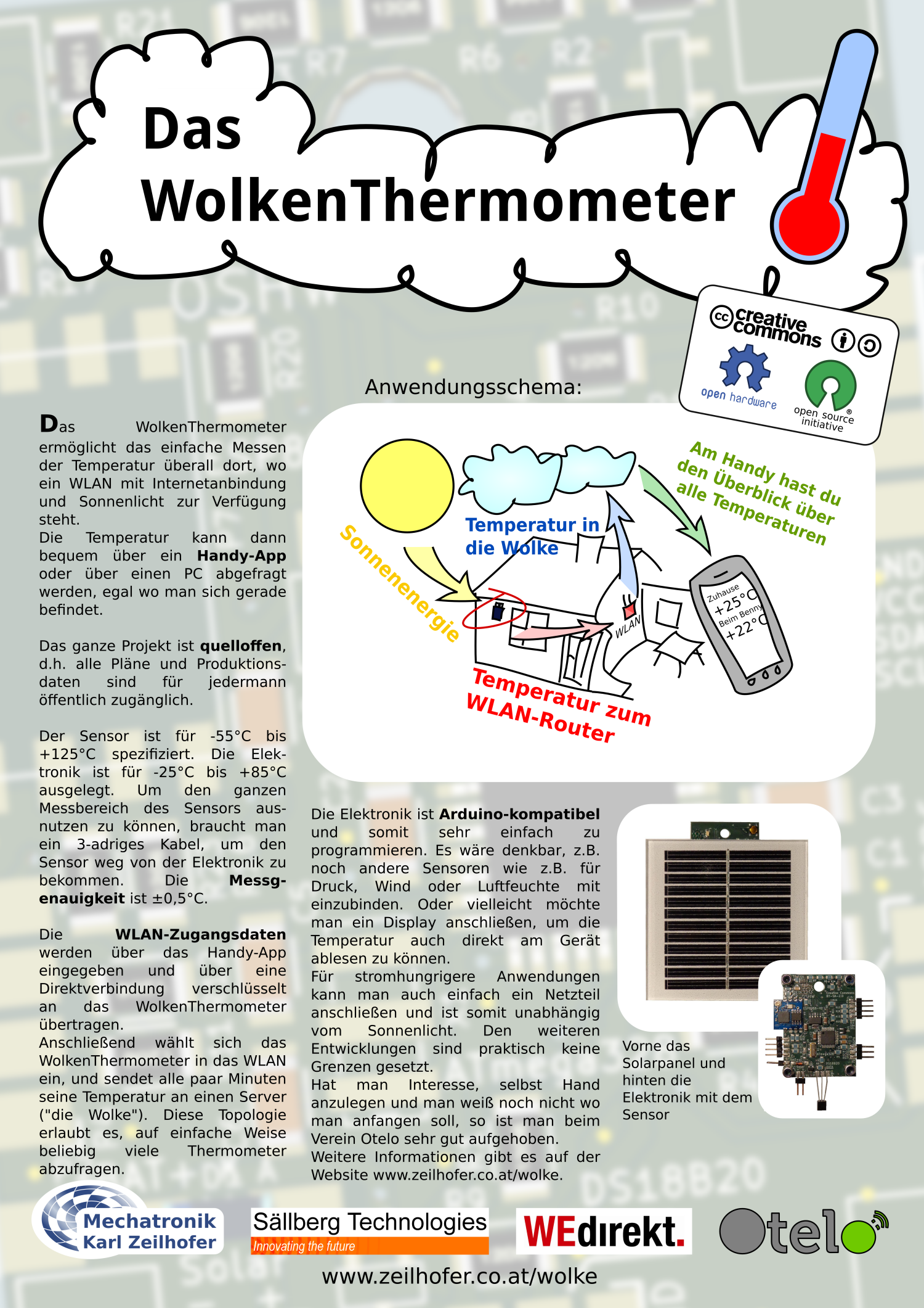
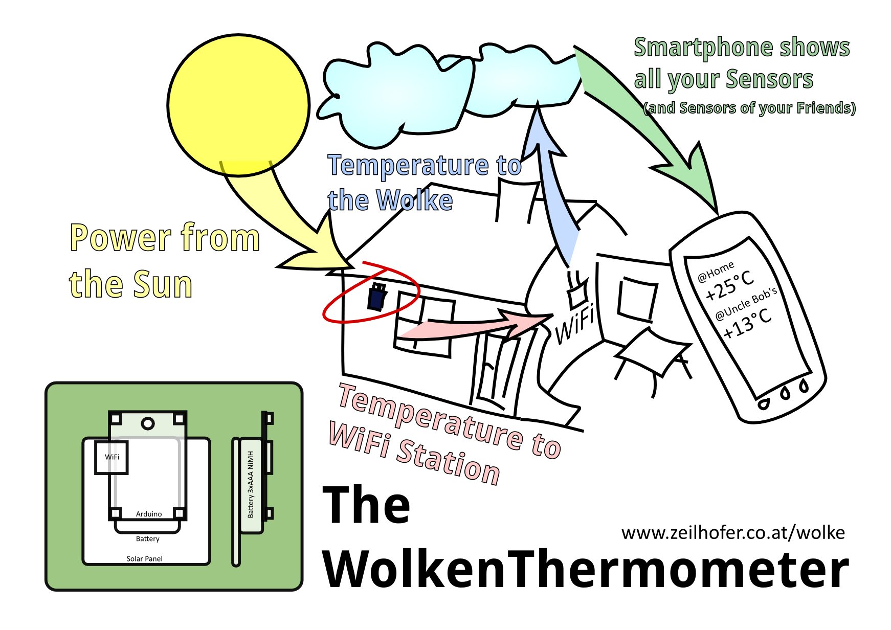 The aim is a compact sensor device with WiFi connection and a temperature sensor.
Put it anywhere in the range of your WiFi at home, and read the measurement value on your smart phone from around the world. It runs on rechargable batteries in combination with a small solar panel and should work for many, many years.
===== Product Design =====
The aim is a compact sensor device with WiFi connection and a temperature sensor.
Put it anywhere in the range of your WiFi at home, and read the measurement value on your smart phone from around the world. It runs on rechargable batteries in combination with a small solar panel and should work for many, many years.
===== Product Design =====
 ===== PCB Preview =====
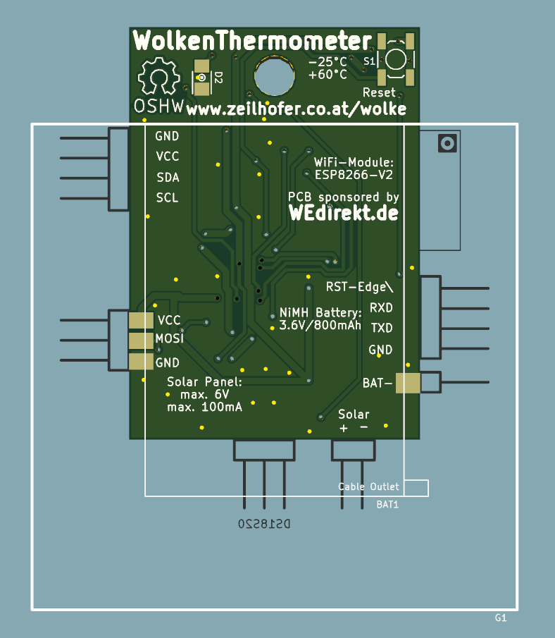
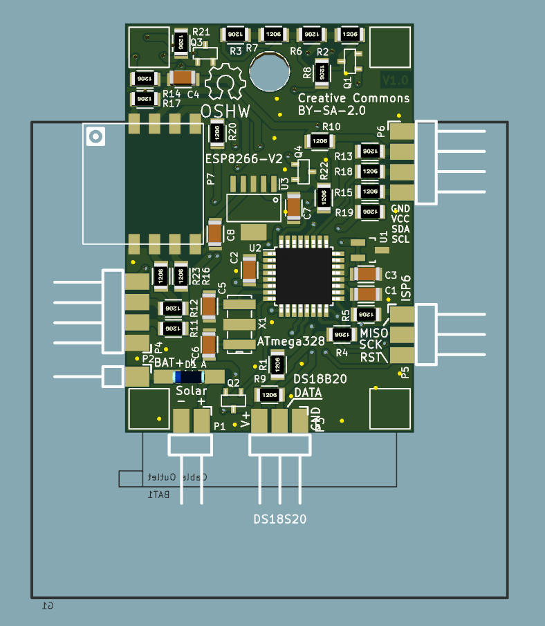 The PCBs for the first batch of 50 pieces including an SMD stencil was kindly sponsored by WEdirekt, the online shop for PCBs and stencils from Würth Elektronik. Please have a look at www.wedirekt.de
 ===== Hardware =====
* ATmega328 with 8MHz resonator (based on the Arduino Nano328)
* WiFi module
* 3.0V voltage regulator with enable pin
* battery pack with 3x NiMH AAA cells (3.6V, 800mAh)
* Temperature sensor DS18B20
* Push button to initialize reconfiguration
* load resistor enabled by the MCU to prevent overcharging of the batteries.
===== Components =====
* WiFi-Sensor (sensor)
* Android smart phone (phone)
* a custom android app (app)
* public web server (server)
===== Protocoll =====
- Download and install the app on your phone
- After pushing the button, it provides its own open WiFi access point.
- Connect your phone to this WiFi network
- the app receives a UDP broadcast packet with a keyword („New-WiFi-Sensor-ID“) the ID of the sensor
===== Hardware =====
* ATmega328 with 8MHz resonator (based on the Arduino Nano328)
* WiFi module
* 3.0V voltage regulator with enable pin
* battery pack with 3x NiMH AAA cells (3.6V, 800mAh)
* Temperature sensor DS18B20
* Push button to initialize reconfiguration
* load resistor enabled by the MCU to prevent overcharging of the batteries.
===== Components =====
* WiFi-Sensor (sensor)
* Android smart phone (phone)
* a custom android app (app)
* public web server (server)
===== Protocoll =====
- Download and install the app on your phone
- After pushing the button, it provides its own open WiFi access point.
- Connect your phone to this WiFi network
- the app receives a UDP broadcast packet with a keyword („New-WiFi-Sensor-ID“) the ID of the sensor
The ID is generated by hashing the MAC address of the WiFi module and the serial number of the temperature sensor.
- enter a name for the sensor (e.g. garden@home)
- enter the SSID and password of your WiFi network at home
- this data is sent as a UDP reply to the sensor
- the SSID and the password are stored in the EEPROM of the microcontroller
- now the sensor goes into its infinite loop, and periodically does following
- turn on WiFi
- connect to the home network
- measure the temperature and battery voltage
- transmit the data to the server
we do here a HTTP GET request with this parameters: ID, temperature, battery status, packet counter, hash
The hash value is generated with the first 4 parameters in combination with a secret key.
- turn off WiFi module
- set timer to 15 minutes
- go to sleep
- wait for timer
- wake up
- repeat
- server checks for correct hash value, by using the same secret key.
- on success the data is stored into a simple text file
- the app does a HTTP GET request for receiving the temperature. The only parameter is the sensor ID.
===== Smartphone App =====
The app will be written with Qt5.4 and therefore has the potential, to run on all three major platforms: Android, iOS and Windows Phone.
For simplicity the common QtWidgets are used instead of the fancy QtQuick user interface. This has some drawbacks in the look-and-feel (for example kinetic scrolling is not implemented), but it is the quickest and most flexible way, at least for me at this moment.
Perhaps the most challanging part will be to support all the different screensizes, which range from 240×320 to 1920×1080 (Full-HD) and more).
==== Qt Evaluation on Android ====
In Qt5.4 Android is supported within QtCreator just out of the box. Connect your Android with USB, hit play and voila! I have described the installation here: android_app_development
With the QMainWindow, Qt provides the native menue on Android. Important to know here is, that the QMenuBar normaly takes QMenue elements, which do not have a triggered()-signal. A workaround is to allways use sub-menus.
The QInputDialog::getText() works as expected. The title-argument isn't visible though. The user has to tap into the line-edit, before the on-screen keyboard comes up. Perhaps self-made dialogs would look better than the predefined ones.
==== Software Concept ====
On the main screen, all the known sensors are shown. They will be in a QVBoxLayout, which is in a scrollArea. This list contains QButtons, which contain dynamically rendered Images, which show all the important Infos about the WolkenSensor. If the user taps on such a button, a detailed QWidget comes up. On an average Screen with about 480×800 pixels at least 5 sensors should be visible without scrolling.
The list covers only about 65% of the screen. The bottom 35% will be used for news-feeds from the developers-group.
=== The main menu ===
will have a structure, similar to this here:
* WolkenThermometer
* Add new Sensor
* Informations
* Help
* Credits
* Contact
* About Qt
===== Hardware Details =====
Here you can download the current version of the schematic, PCB files and the bill of materials:
https://github.com/KarlZeilhofer/WolkenThermometer-kicad
==== Measuring Battery Voltage ====
We use the internal ADC and an external shunt reference (LM431SCCM32X, RS#806-4043 for 6.5€ct/pc).
Pin D9 is used as an output, which drives the gate of a P-MOSFET, which in turn powers the reference voltage, the voltage devider and the temperature sensor. The voltage devider is used to reduce the analog battery voltage from 0…5V to 0…2.5V (1k+1k).
==== Driving the Temperature Sensor ====
The temperature sensor is a digital one wire sensor with a resolution of 12 Bit with an LSB corresponds to 62.5mK. The resolution can be reduced to save current consumption, since the result is returned faster with lower resolution.
It's stand by current is only 1uA, but it is totally switched off with a P-MOSFET like the analog battery voltage measuring and the voltage reference.
==== Reset Circuit ====
We have some different sources for a system reset:
- Power-On-Reset
normally it should appear just once in a life time of the product, or when the battery is replaced.
- Reset Button
For resetting the WolkenThermometer to it's factory settings, the reset button should be pushed and held for 10 seconds, until the LED is flashing. The button disables the WiFi module, and ties the reset pin low for a short time. So on bootup we can check, if the button is pressed for 10s, and erase the EEPROM content and go into configure mode.
- Arduino-Programming Interface
The DTR-output of a USB ot UART converter also goes onto the reset over the coupling capacitor. A reset is triggered, when the DTR-line goes low. This enables the Arduino IDE to automatically start the boot loader, and send the firmware via the TxD and RxD lines.
- ISP Connector
The last source is the ISP connector, which has a direct connection to the reset pin.
==== Resonator ====
We use here a simple ceramic resonator with 8MHz. It's initial accuracy is ±0.5%, and over the whole temperature range (-20…+80°C) it is ±0.8%. This should be fine for reliable UART communication with the WiFi module.
==== Level Conversion for WiFi-UART ====
==== Load Resistors ====
To protect the battery from overcharge, the controller can enable load resistors, which draw up to 116mA @ 4.35V. So even in the brightest sunlight the batteries are kept in a save area of operation.
==== In System Programming ====
For flashing the firmware into the chip, the ISP connector is used. We use it at least for an Arduino bootloader. From then, the firmware can be donwloaded with a simple USB-UART converter.
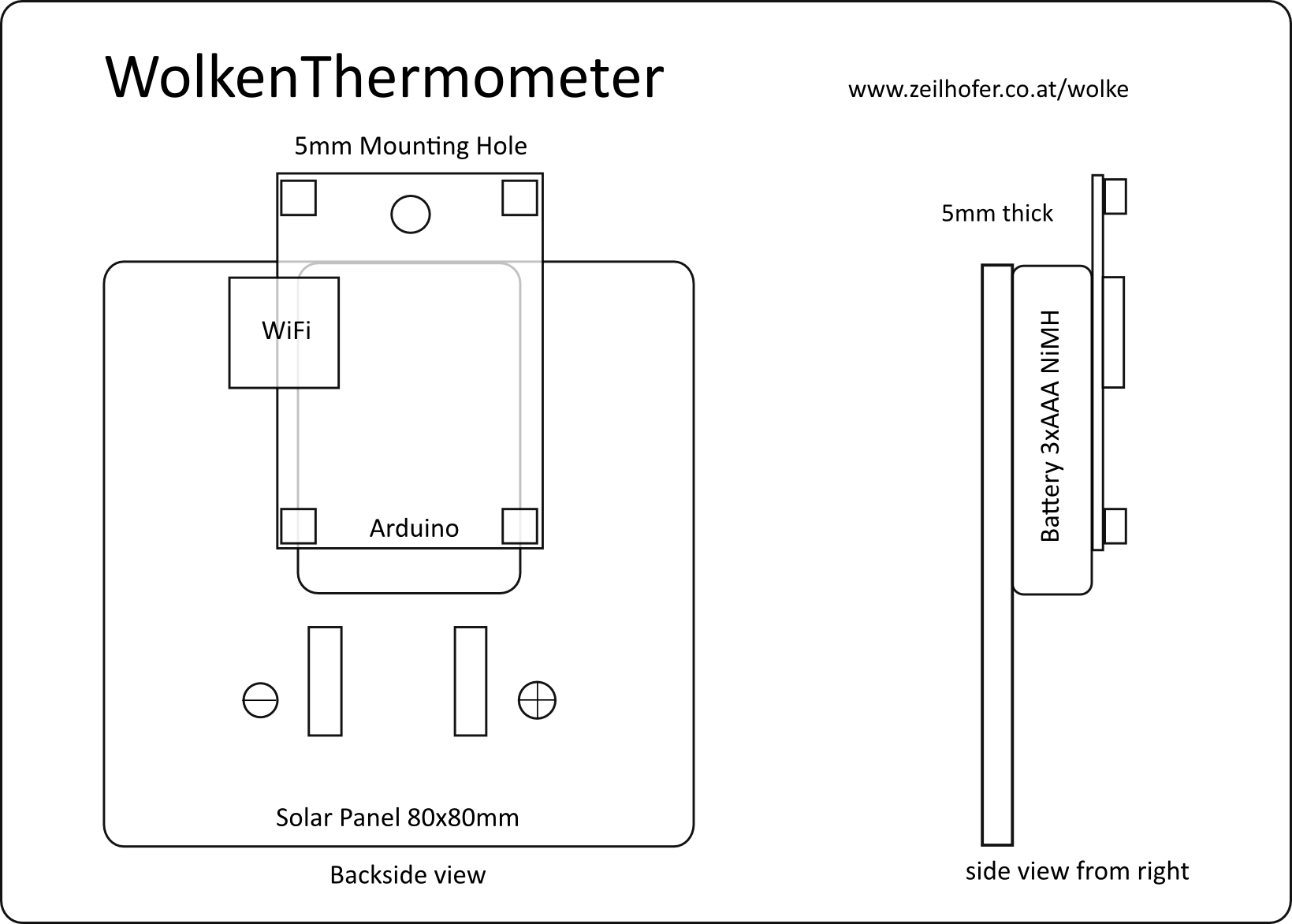
==== Solar Panel ====
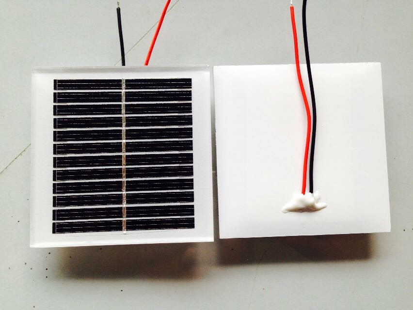 The solar panel is has a size of 80x80mm and is 5mm thick. It is a laminated glass panel, which the optimum technology for long life time (20 years and more). We also had the option to buy cheaper epoxy sealed panels, buth their life time is about 2-3 or perhaps 5 years, depending on who you ask.
It's nominal ratings are 6V/100mA/0.6W. In winter days a solar panel harvests about 1h of nominal power, which is 100mAh in our case. This means, we could have in such a situation an average current consumption of about 4.2mA. If we assume the average WiFi current with 100mA, we need a sleep to transmit ratio of about 24. If one transmit, including dailing into the WiFi needs about 10s, then we can send a packet every 240s = 4 minutes.
In summer we get about 4 times the energy in a day than in a winter day. Which leads to a transmit period of 1 minute.
One has to keep in mind, that direct sun light leads to an error in temperature mesurement, if the sensor is soldered directly to the PCB. We recommend to use a short cable (max. 1m) to put the sensor in a good place for measuring the ambient temperature, and mentaining a good orientation of the solar panel to the sun light.
For indoor measuring it will be necessary to put the WolkenThermometer either directly to or onto a window, or to a light bulb, which is used regularly.
The user allways can monitor the battery condition with the app for the smart phone.
==== Battery Pack ====
The battery is assembled out of 3 pieces of AAA NiMH cells. In total we have nominal 3.6V and 800mAh.
Instead of the NiMH battery, a lithium battery will be used, since the NiMH type is not able to deliver enough current at cold temperatures.
If the solar panel delivers enough power, we can increase the data transmission frequency. If the thermometer is in a rather dark area, we reduce the frequency to save power.
Exact measurements on power consumption of the WiFi module and also the whole circuit it self have to be done, to calculate the optimum function for transmission rate.
===== Firmware Details =====
Here you can find the source code on Github:
https://github.com/KarlZeilhofer/WolkenThermometer-firmware
==== Structure ====
We have thes main states:
- Setup-Config
Wait for configuration of ID, Public-Key and Secret-Key via UART.
This state is entered, when no configuration has happened or when the reset button is pressed for 20-30 seconds.
LED is permanent on.
- WiFi-Config
Wait for incomint TCP connection from smart phone app for setting WiFi SSID and password
This state is entered, when no configuration has happened or when the reset button is pressed for 5-10 seconds.
LED is flashing once in a second.
- Measure
temperature and send it to the server
This state is entered, when all configurations are set. LED flashes once every 8 seconds.
- ConfigFailed
If we get no valid configuration, then we turn all peripherals to minimum power consmption and wait for a button reset. The LED flashes tree times every 8 seconds.
=== On Power Up or Reset ===
The reset button has 3 functions.
- trigger a reset impulse via a impulse couple capacitor
- usded as general purpose input for entering different configure modes
- when pressed, the WiFi module is deactivated
<code>
if keys are configured and reset button pressed, count seconds until release
if 5-10s: open accesspoint, transmit UDP broadcast message and wait for incoming TCP connection
if 20-30s: call serial setup menu.
else check for proper configured keys and ssid in the eeprom
if all is fine, go into measure-loop
else go into corresponding configure-state
</code>
==== Power Save Mode and Timer ====
We use the watch dog timer, which runs on an internally RC ocillator with 125kHz. It's max. period is 8s.
The watchdog can be configured, to trigger onyl an interrupt, without rebooting the controller. That's what we need here. 8s is too short, so we have to count several times 8s, and this only works, if we can use variables in RAM. This probably wouldn't work, when the controller reboots every timer period.
===== The Server Software =====
The software running on a publicly accessable server is kindly contributed by Sällberg Technologies. This company is focused on digital signal processing and application engineering. Please have a look at www.sallberg.at.
 The main components which are used are PHP and MySQL.
A PHP script takes the parameters from a HTTP GET request, sent by the WolkenThermometer to the server, and stores them into the MySQL data base. For security reasons the data gets signed by a secret key, which is known to the WolkenThermometer itself and to the server. It is generated on device production, and then stored in the EEPROM.
For getting the measured data from the server, a client, which could be a webbrowser or a smart phone, sends an HTTP-GET request to the server, and a proprietary, human readable text is returned with the desired values.
===== Extras =====
* server stores all the received values, and the app can show graphs and statistics
* The user can add muliple sensor IDs in his app. So one can use multiple sensor in one home, or get data from a friends WiFi sensor.
* The reply message from the app to the sensor with SSID and password could be encrypted with a secret key
* In addition to the smartphone app a desktop application could also be provided, but a webaccess through a webbrowser seems to be more appropriate.
===== Research Links =====
* Arduino Pro, ATtiny328 on 3.3V/8MHz Crystal
The main components which are used are PHP and MySQL.
A PHP script takes the parameters from a HTTP GET request, sent by the WolkenThermometer to the server, and stores them into the MySQL data base. For security reasons the data gets signed by a secret key, which is known to the WolkenThermometer itself and to the server. It is generated on device production, and then stored in the EEPROM.
For getting the measured data from the server, a client, which could be a webbrowser or a smart phone, sends an HTTP-GET request to the server, and a proprietary, human readable text is returned with the desired values.
===== Extras =====
* server stores all the received values, and the app can show graphs and statistics
* The user can add muliple sensor IDs in his app. So one can use multiple sensor in one home, or get data from a friends WiFi sensor.
* The reply message from the app to the sensor with SSID and password could be encrypted with a secret key
* In addition to the smartphone app a desktop application could also be provided, but a webaccess through a webbrowser seems to be more appropriate.
===== Research Links =====
* Arduino Pro, ATtiny328 on 3.3V/8MHz Crystal
http://www.arduino.cc/en/Guide/ArduinoPro
* Arduino Eclipse
http://www.baeyens.it/eclipse/
* Dirt Cheap Electronics, loading bootloader with Arduino
http://blog.roguecode.co.za/make-dirt-cheap-electronics-with-attiny45-arduino-nano/
* bootloader that comes with the Arduino IDE
file:///usr/share/arduino/hardware/arduino/bootloaders/atmega/ATmegaBOOT_168_atmega328_pro_8MHz.hex
* DS18B20 auf eBay €1,20/Stk
http://www.ebay.at/itm/10-DS18B20-Digital-Temperature-Sensor-Thermperatursensor-TO92-55-C-125-C-/270830089706?pt=Bauteile&hash=item3f0ebb35ea
* DS18B20 datasheet
http://datasheets.maximintegrated.com/en/ds/DS18B20.pdf
* SHA1 in c
https://github.com/jasinb/sha1
* SHA1 in java
http://www.herongyang.com/Cryptography/SHA1-Message-Digest-in-Java.html
* SHA1 in php
http://php.net/manual/en/function.sha1.php
* 3.0V LDO 5uA power-down
http://at.farnell.com/rohm/bd30ic0wefj-e2/ldo-fixed-3v-1a-htsop-8/dp/2342918
* ESP8266 Wiki
https://github.com/esp8266/esp8266-wiki/wiki
* Number base converter:
http://convertxy.com/index.php/numberbases/
this is useful for base-64 conversion
* Online Calculators:
* string length http://string-functions.com/length.aspx
* sha1
* for strings: http://www.sha1-online.com/
* for files: https://md5file.com/calculator
* aes256: http://aes.online-domain-tools.com/
* AVR Fuse Calculator http://www.engbedded.com/fusecalc/