
sbms4080
Inhaltsverzeichnis
Notes on the Solar BMS SBMS4080
5.4.2017
Some years ago I've bought the solar BMS from Dacian Todea, a very smart guy from Canada, who has set up a kickstarter campaign for an open source hardware.
I chose the DIY kit.
Yesterday I've soldered the PCBs, since with my new project, the Nachtsonne I have a use for this now.
There were some issues, which I think are woth noting.
Technical Data
Power Dissipation
Without any heatsink, 6W of dissipation on the power MOSFETs is possible. With Heatsink more than 20W are possible.
PV-Input
6mV/A –> 9.6W@40A
Load-Outpt
2mV/A –> 0.8W@20A
Missing Parts
The DIY kit came with nearly all the necessary parts needed for the assembly. All the 1k resistor packs were missing, but I could successfully replace them with 1608 metric (0603 imperial) resistors.
Part Values
I've found 3 different versions for the part values. The probably most fitting ones are the one from the KiCad schematic from August 2014. An earlier version from May and also the PCB-file from August has more 220nF instead of the updated 1uF ceramic capacitors.
I'v got also an 270R R-pack, but there was no use for it.
Orientation of the Box Header Connectors
The box headers have a pin1 designator, both on the plug and on the socket, but Dacian didn't comply with this scheme. Therefore the printings on the top of the BMS are incorrect. Changes have to be made in the schematics and on the printing on the device.
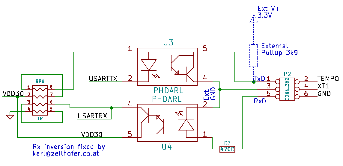
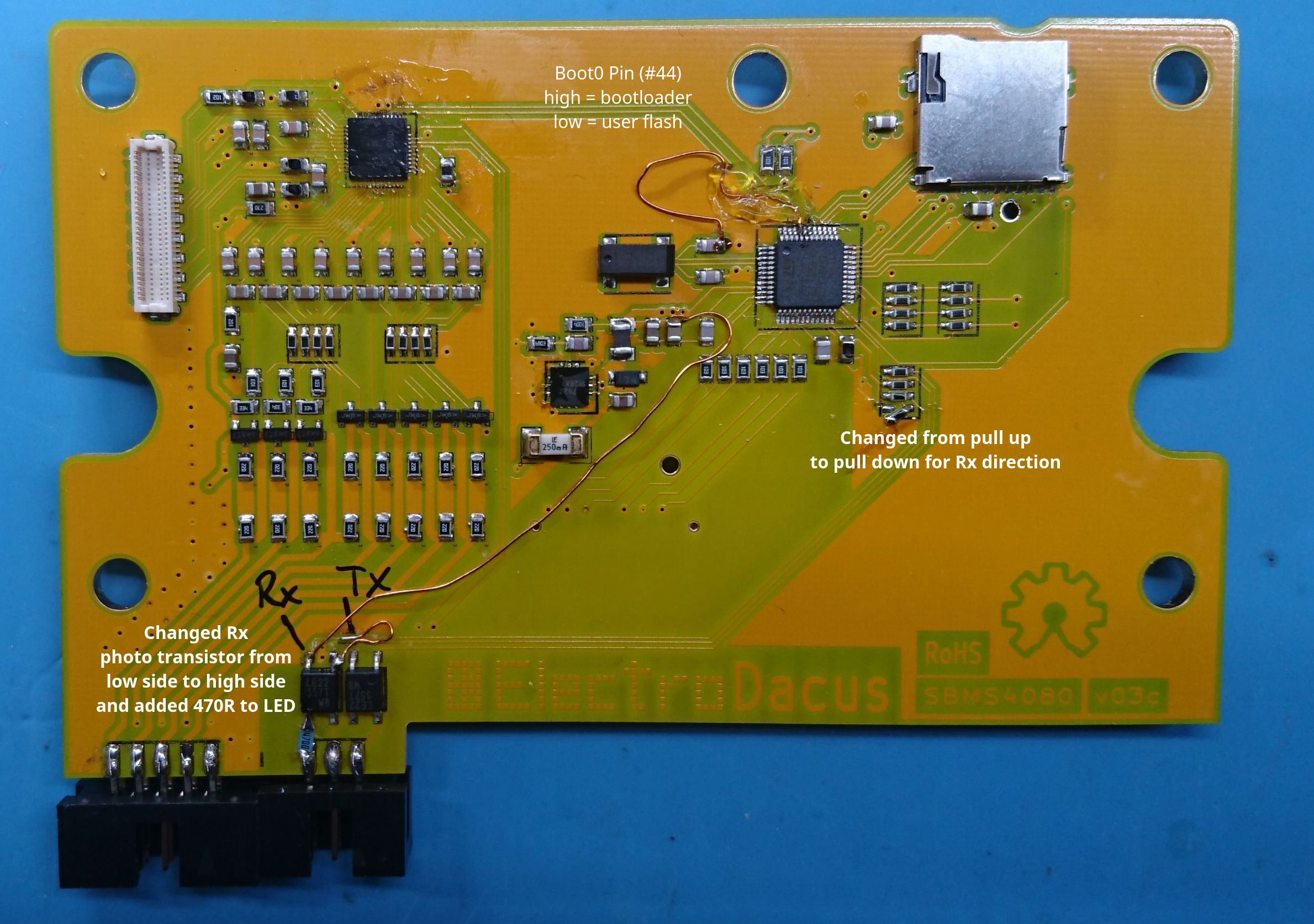
Rx and Tx
The UART is connected to external pins via opto coupplers. Somehow the Tx line is without negation, and the Rx line is negated. I've fixed this with some enameled copper wire and resistors.
Fixed Version:
Flashing the Firmware
For flashing the firmware I've used the Rx and Tx lines, connected to the external pins1). As USB adapter I've used the FTDI converter to 3.3V UART, with an 3.9k Ohm external pullup for the BMS's Tx line.
The Boot0 pin (pin 44 of the MCU) is floating by default. For programming it has to be connected to VCC (3.0V).
As software I used the STM32 Flash Loader Demonstrator with 9.6kbit/s and 128kByte Flash size settings. Sadly this software only runs on windows.
After flashing, Boot0 pin has to be connected to GND.
Dacian explains here how to use a ST Microselectronics developmentboard to programm it via USB.
Mechanical Tolerances Missmatch of LCD
The LCD loses the signal very easy. It helps, to move the LCD as far to the North as possible before mounting the top PCB with the capacitive touch sensors. I also removed the zebra conductor from the LCD and cleaned all surfaces with „Kontaktspray“. Since then there was no problem any more.
1)
they have been fixed, see Rx_and_Tx
sbms4080.txt · Zuletzt geändert: von karl